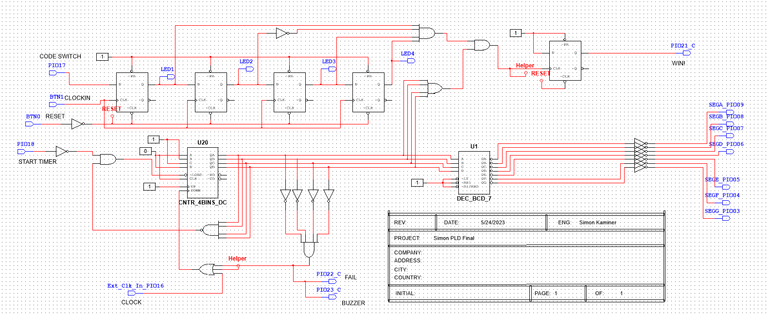
Above is a game I created in Multisim, a desktop circuit simulator. The point of the game is to input the correct code to the shift register, seen at the top, before time runs out.
The timing mechanism is at the bottom. This timing mechanism is created through the use of an IC counter. The various logic around these two main elements are in place to check whether the right code was put in or not, and stop the game or reset it.
If the correct code is not put in in time, the buzzer sounds.

Seen here is the input part of the program. There is a display and multiple buttons and switches which are connected through off screen connecters to the actual circuit.

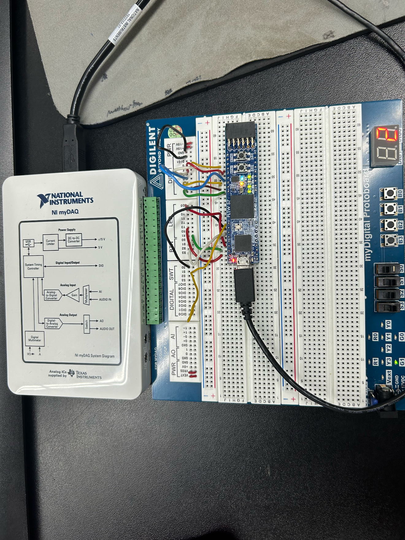
The above image is a physical representation of my Multisim Program. There is a 7-segment display on the right to count, while the buttons and switches on the circuit board represent the buttons and switches in the code.

While the above circuit looks similar to the first circuit shown, it is slightly different. This circuit is used to link the Multisim circuit to the Programmable Logic Device (PLD), so the game becomes physical. Most aspects of this code are the same, but the buttons and switches are linked to real buttons and switches on the PLD that are linked when the circuit is downloaded.