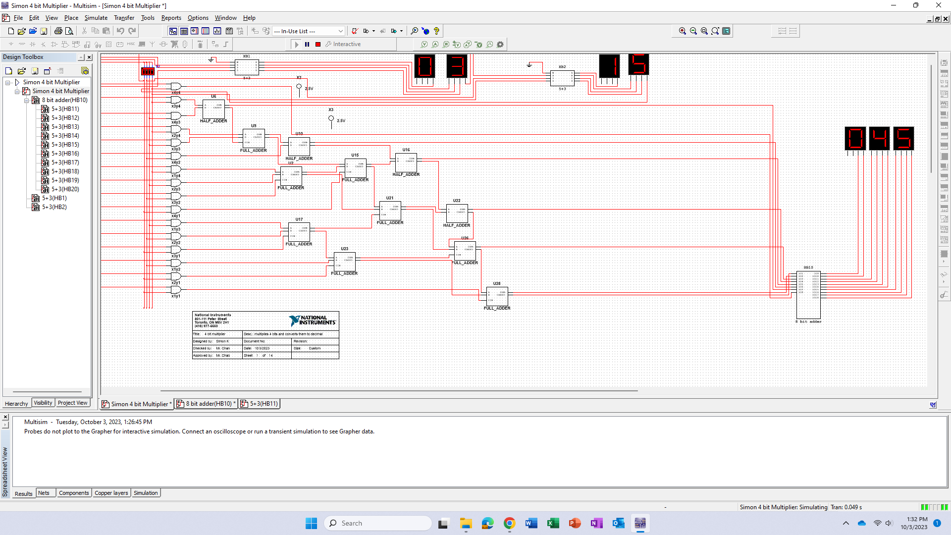
This is a typical multiplier in digital electronics, with an added twist. Seen in the above photo, there are multiple half adders and full adders to complete the action
of actually multiplying the two 4bit numbers (albeit in binary format).
The binary numbers, input with switches on the left side of the screen, are then run through a subcircuit labeled '5+3'
that converts the binary numbers to decimal format.
This is then run through a larger version of these subcircuits, which allow an 8 bit number to be converted from binary to decimal. This
is labeled '8 bit adder'.

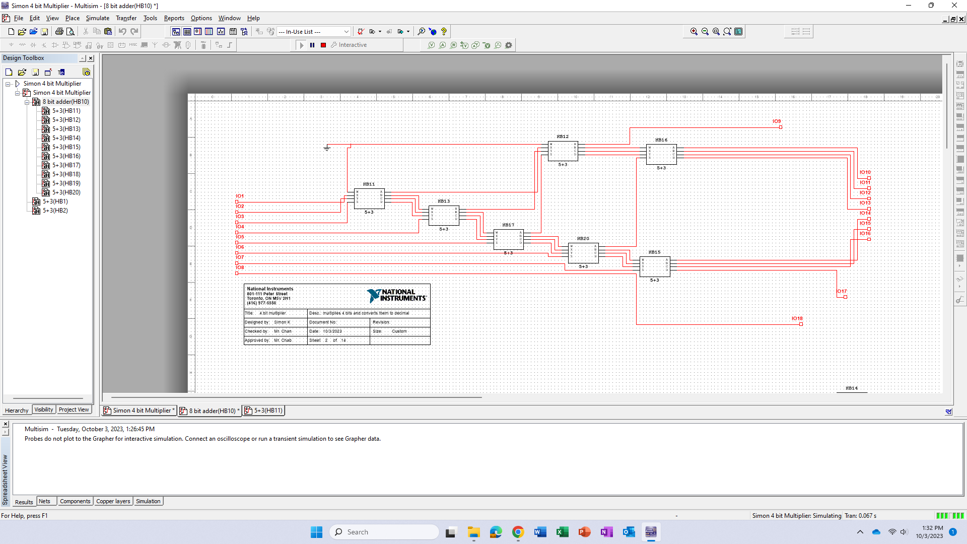
This is the inside of the 8 bit adder subcircuit. Seen here are multiple iterations of the 5+3 converter, which is explained in more detail below. This subcircuit essentially
takes an 8 bit number, in decimal, and runs it through a formula, to convert it into a format which it can be displayed in decimal as the same number.
This circuit requires 10 outputs for 8
inputs. This is because the largest binary number in 8 bit format is 225. When displaying this, it needs three different displays, for three different numbers.
The first number displayed can either
be a 0, 1, or 2 - this is a two bit number, as the largest number is 2, which is 10 in binary. The next two digits can be 0-9, as there numbers like 199 or 049 can be displayed. 9 is a 4 bit binary
number - 1001.
For three displays, 10 different outputs are needed to display any possible combination of the converter.
The binary number is run through multiple 5+3 checkers, and shifted after every check. This is the formula to convert binary to decimal works.
The shift can be seen with most significant bit output from each checker moved into a separate row of checkers at the top.

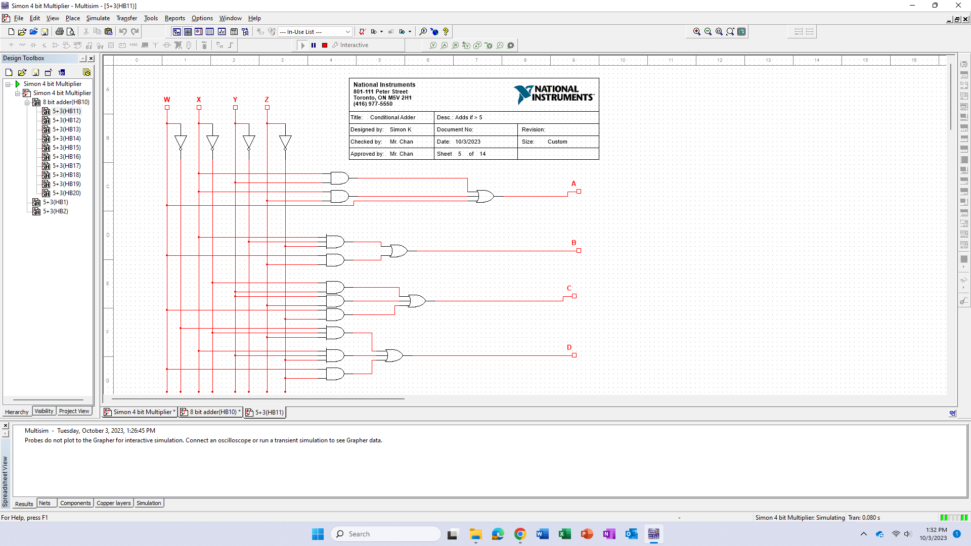
This is the logic on the inside of the 5+3 converter circuit. These circuits input a 4 bit binary number (up to 15). It is then run through a checker.
This checker checks if the binary number inputted is greater than or equal to 5. If this is true, 3 is added to the binary number. If this is false, the binary number stays the same.
This logic is represented in the gates above, which take the number and convert the binary to an equal decimal format.